Inversion, as a key power conversion process, is about efficiently converting direct current (DC) into alternating current (AC). As the implementer of this conversion process, photovoltaic inverters not only play a pivotal role in solar power generation systems but also serve as a bridge between renewable energy and the power grid. This blog aims to deeply analyze the composition, classification, and core parameters of inverters and provide detailed guidance for your selection.
What are the Main Components of an Inverter?
- Enclosure & Terminal Connections: Provide physical protection for the internal circuits while ensuring safe and convenient wiring.
- Cooling System: Adopting an efficient heat dissipation design, such as a heat sink, fan, or liquid cooling system, to ensure that the inverter can still maintain a suitable working temperature during high-load operation.
- Display Screen: Visualize the working status, fault information, and operation data of the inverter, which is convenient for monitoring and maintenance.
- Control Board: As the “brain” of the inverter, it is responsible for power control, algorithm operation and fault diagnosis to ensure efficient and stable operation of the system.
- Power Supply Module: Provides a stable and reliable DC power supply for each component inside the inverter.
- Power Conversion Module (Power Board): The "heart" of the inverter, responsible for converting the input DC power into the required AC power, its design directly affects the conversion efficiency and output quality.
What is the Classification of Inverters?
- By Function: Grid-connected inverter (operating in parallel with the grid) and off-grid inverter (independent power supply system).
- By AC Output Frequency: Industrial frequency inverter (frequency: 50- 60Hz), medium frequency inverter (frequency: 400Hz-20kHz), and high frequency inverter (frequency: >20kHz).
- By Output Phase: Single-phase, three-phase, and multi-phase inverters to meet different load requirements.
- By PV Module Connection: Centralized inverter (suitable for large photovoltaic power stations), string inverter (small and medium-sized power stations and distributed power generation), and micro inverter (household or small system).
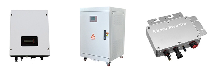
Comparison of Three Different Inverter Types
| Centralized Inverter | String Inverter | Micro Inverter | |
| Definition | Connects multiple PV strings to a single large inverter. | Uses a modular approach where each PV string is connected to an individual inverter, forming a combined system. | Each PV module is paired with a dedicated microinverter with independent inversion and MPPT functions, mounted directly on the module. |
| Advantages | 1. High power output, fewer units, easy management; fewer components, better stability, and easier maintenance. 2. Low harmonic distortion, high power quality; comprehensive protection features, high safety. 3. Supports power factor adjustment and low voltage ride-through, improving grid adaptability. |
1. Minimizes power loss due to module differences or shading, maximizing energy generation. 2. Wide MPPT voltage range allows flexible PV module configuration; longer operation in low-light conditions. 3. Compact size, small footprint, no need for a dedicated room; low self-consumption, and minimal fault impact. |
1. Maximizes energy output. 2. Balances voltage and current across all PV modules, preventing system imbalance. 3. Each unit has monitoring capabilities, reducing maintenance costs and improving reliability. 4. No high-voltage DC, enhancing safety; easy installation and maintenance, enabling DIY solar setups. 5. Cost comparable to or lower than centralized inverters. |
| Disadvantages | 1. Narrow MPPT voltage range; cannot monitor individual PV strings, reducing optimization and flexibility. 2. Requires ample space and a dedicated room, limiting installation flexibility. 3. High self-consumption and additional power required for ventilation and cooling. |
1. Small electrical clearance in power components, unsuitable for high-altitude areas; more integrated components may reduce stability. 2. Outdoor installation exposes the casing and heat sink to weathering and aging. 3. Higher unit count increases overall failure rate and monitoring complexity. |
1. Higher unit count for the same installed capacity. 2. Long-term performance in safety, stability, and energy yield requires further validation in large-scale projects. |
What are the Important Parameters of an Inverter?
1. DC Input Parameters
- Maximum PV String Power: Defines the maximum DC input power that the inverter can safely handle.
- Rated DC Power: Comprehensively considers conversion efficiency and redundant design to ensure stable operation of the inverter under rated conditions.
- Maximum DC Voltage: Under the premise of considering the temperature coefficient, the maximum voltage of the connected PV string must be less than the maximum DC input voltage of the inverter.
- MPPT Voltage Range: The MPPT voltage of the PV string, considering the temperature coefficient, must be within the MPPT tracking range of the inverter. A wider MPPT voltage range can achieve more power generation.
- Start-up Voltage: The inverter starts when the starting voltage threshold is exceeded and shuts down when it falls below the starting voltage threshold.
- Maximum DC Current: When selecting an inverter, the maximum DC parameter should be taken into consideration, especially when connecting thin film PV modules, to ensure that the current of the PV string connected to each MPPT is less than the maximum DC of the inverter.
- Input Channels & MPPT Inputs: The number of input channels of the inverter refers to the number of DC input channels, while the number of MPPT channels refers to the number of maximum power point tracking channels. The number of input channels of the inverter is not equal to the number of MPPT channels. If the inverter has 6 DC inputs, each of the three inverter inputs will be used as an MPPT input. 1 MPPT input for several PV strings needs to be equal, and the PV string inputs under different MPPTs can be unequal.
2. AC Output Parameters
- Maximum AC Power: Maximum AC power refers to the maximum power that the inverter can generate. Generally speaking, the inverter is named according to the AC output power, but it is also named according to the rated power of the DC input.
- Maximum AC Current: Maximum AC refers to the maximum current that the inverter can generate, which directly determines the cross-sectional area of the cable and the parameter specifications of the power distribution equipment. Generally speaking, the specifications of the circuit breaker should be selected to be 1.25 times the maximum AC.
- Rated Output: Rated output has two kinds of frequency output and voltage output. In the United States and Canada, the frequency output is generally 60Hz for industrial frequency, and the deviation should be within +1% under normal working conditions. Voltage output has 208V, 240V, 480V, and so on.
- Power Factor (PF): In an AC circuit, the cosine of the phase difference (Φ) between voltage and current is called the power factor, which is represented by the symbol cosΦ. Numerically, the power factor is the ratio of active power to apparent power, that is, cosΦ=P/S. The power factor of resistive loads such as incandescent bulbs and resistance furnaces is 1, and the power factor of inductive load circuits is less than 1.
3. Efficiency Metrics
Four types of efficiency are commonly used in inverters: maximum efficiency, European efficiency, MPPT efficiency, and whole machine efficiency.
- Maximum Efficiency: Refers to the peak conversion efficiency of the inverter at an instant.
- European Efficiency: It is the weights of different power points derived from different DC input power points, such as 5%, 10%, 15%, 25%, 30%, 50% and 100%, according to the light conditions in Europe, which is used to estimate the overall efficiency of the inverter.
- MPPT Efficiency: Reflects the accuracy and efficiency of the inverter tracking the maximum power point.
- Overall Efficiency: Refers to the product of European efficiency and MPPT efficiency at a certain DC voltage.
4. Functional Protection Parameters
- Islanding Protection: When the power grid loses voltage, a solar power system may continue supplying electricity to a section of the de-energized grid. Islanding protection is designed to prevent this unintentional islanding effect, ensuring the safety of grid operators and users while reducing faults in distribution equipment and connected loads.
- Input Overvoltage Protection: This function prevents the solar inverter from starting or forces it to shut down when the DC input voltage exceeds the maximum allowable limit for the inverter's DC array connection.
- Output Overvoltage/Undervoltage Protection: This protection mechanism activates when the inverter's output voltage exceeds the maximum allowable output voltage or drops below the minimum allowable output voltage. The inverter's response time to abnormal AC voltage must comply with specific grid connection standards.
Conclusion
Inverters are crucial in PV systems. A thorough understanding of their structure, classifications, and key parameters is essential for selecting and configuring an efficient and reliable solar power system. By considering application scenarios, system scale, budget, and future expansion needs, you can choose the best inverter to support your solar power journey.