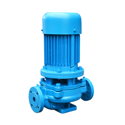
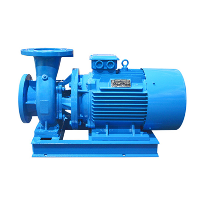
4 hp Horizontal Centrifugal Pump with 16.3m3/h maximum flow, 33m maximum head, and 50mm diameter of inlet and outlet.
Features:
- The centrifugal pump has a horizontal structure. The diameter of the inlet and outlet are the same. If a protective cover is added, it can be used in the open air.
- It is easy to install and maintain. There is no need to dismantle the pipeline system, just lift off the conjunction flat nut of the vertical pump. Then, all the rotor parts can be taken out.
- A horizontal centrifugal pump can operate in series and parallel connection according to the requirements of flow and head.
- The installation angle of the pump outlet can be 0°, 90°, or 180° to meet different connection occasions.
Specifications:
| Model |
ATO-HCP-50-160 |
| Weight |
80kg |
| Size |
370*560*250mm |
| Power |
4 hp (3kW) |
| Phase |
3 phase |
| Input voltage * |
AC 220V, 230V, 240V, 380V, 400V, 415V, 440V, 460V, 480V |
| Input frequency * |
50Hz, 60Hz |
| Flow (min. flow to max. flow) |
8.8m3/h (38.7 gpm, American system) |
12.5m3/h (55 gpm, American system) |
16.3m3/h (71.8 gpm, American system) |
| Head (max. head to min. head) |
33m (108ft) |
32m (105ft) |
30m (98ft) |
| Efficiency |
45% |
52% |
51% |
| Inlet diameter |
50mm (2 inch) |
| Outlet diameter |
50mm (2 inch) |
| Installation angle of outlet |
0°, 90° and 180° |
| Nominal diameter of impeller |
160mm |
| Pump type |
Booster pump |
| Number of stages |
Single stage |
| Motor type |
Y/Y2 series motor |
| Motor speed |
2900rpm |
| Impeller material |
304/316 stainless steel |
| Seal material |
304 stainless steel, tungsten carbide, fluorine rubber |
| Inlet max. pressure |
1MPa (145 psi) |
| (NPSH)r |
2.3m |
| Usage |
Water or liquids compatible with pump component materials.
1. The volume of solid particles should be less than 0.1% in unit volume, and the granularity should be less than 0.2mm.
2. The temperature should be lower than 60℃. |
| Environment |
Temperature: <40℃, humidity: <95%, altitude<1000m |
| Warranty |
12 months |
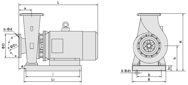
Horizontal centrifugal pump dimension (unit: mm):
| Boundary dimension |
Base dimension |
Flange dimension |
| h |
H |
L |
a |
A |
L1 |
B |
l |
b |
h1 |
4-Φd1 |
D |
D1 |
n-Φd |
| 210 |
370 |
560 |
80 |
55 |
400 |
250 |
350 |
150 |
80 |
4-Φ14 |
Φ165 |
Φ125 |
4-Φ18 |

Tips: Optimizing and transforming methods of the centrifugal pump
As everyone knows, during the daily water supply operation of the pump, the water-using period is divided into the peak period and the low peak period according to the different water use times. The amount of water used by the user varies greatly, and the water demand of the system is less than the flow rate of the design condition point most of the time.
However, in the engineering design process, the pump parameters are determined, and pump models are selected according to the most unfavourable working conditions. Due to the incompressibility of water, when the water supply of the pump is greater than the water demand of the system, the pressure of the entire system will increase. At this time, according to the characteristics of the water pump, the operating point of the water pump will move to the side with a rising head and decreasing flow rate. When the flow rate is reduced to a certain value, the pump will deviate from the high-efficiency section. When the flow rate is reduced, the loss of the pipeline system is reduced, and the head required by the system is also continuously reduced so that the head of the water pump is often in an excess state. As a result, not only is the user's water pressure in the over-pressure status, which will bring water using inconvenience to water, but also it will cause energy waste.
To meet the user's water use requirements and economic operation objective, the pump flow rate and head are usually required to be changed to vary the working point. The operating point of the centrifugal pump is determined by the characteristics of the pump and the characteristics of the piping jointly. To realize the economic operation in the pumping station, the operating conditions of the pump must be adjusted. The specific means include:
- Adjust the throttling valve (change pipeline resistance)
- Adjust the guiding blade at the entrance (change the blade installation angle)
- Change the impeller diameter
- Change the revolving speed of the pump
In this case, the adjustment throttling valve realizes the working condition regulation by changing the pipeline characteristic curve, and the throttling valve achieves this through increasing the pipeline resistance and reducing the flow rate. This adjustment method is uneconomical. Increasing the resistance of the pipeline is equivalent to increasing the pipeline loss. After the flow rate is lowered, the power drop is not obvious. There is also a cavitation problem in the adjustment of the throttling valve of the pump suction end, so this method cannot effectively adjust the flow rate.
The adjustment of the inlet guiding blade is the basic method of the flow rate adjustment of the pump, and the Q-H characteristic curve can be changed to achieve the flow regulation purpose. At this moment, the power is roughly in direct proportion to the flow rate, and the power required to regulate the outlet valve is relatively small.
The adjustment means of changing the impeller diameter cannot be used as a real-time adjustment, so this method has a greater limitation in application. Only the angle and speed changing regulation can be used for real-time adjustment, and the speed changing adjustment has the advantages of wider adjustment range, higher adjustment efficiency, and stronger operability compared with the angle changing regulation. Of course, for large and medium-sized axial and mixed-flow pumps, angle-changing adjustments can be used to adjust the working conditions of the pump. However, for small centrifugal pumps, the working condition point of the water pump is changed by varying the revolving speed of the water pump. Therefore, the centrifugal pump flow adjustment adopts the revolving speed adjustment.


